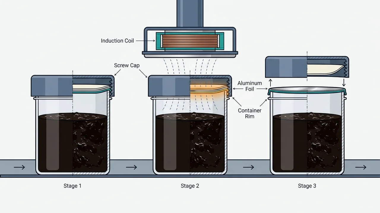
An induction foil seal is a non-contact electromagnetic process that welds a multi-layer aluminum foil inner liner to a plastic or glass container lip after filling and screw capping. Eddy currents heat the foil, melt wax into the pulp backing, and fuse a resin-matched polymer film onto a clean, uniformly torqued jar rim to prevent leaks.
For rigid hookah jars and wide-mouth tubs, seal reliability starts before the induction head. Pair your container resin with the right liner laminate, keep sticky tobacco and syrup off the rim during filling on a shisha tobacco filling and weighing machine, and compare rigid jars with flexible bags in our shisha tobacco packaging formats guide.
What Is an Induction Foil Seal and How Does Non-Contact Heating Work?
Induction sealing bonds thermoplastic materials without physical heater contact by passing a filled, capped container beneath an oscillating electromagnetic coil that induces eddy currents inside the aluminum foil liner, melting wax into the paper pulp backing and fusing the bottom polymer film to the container lip upon cooling.
Because heating happens inside the conductive aluminum foil after the closure is already in place, the process hermetically seals both plastic and glass containers without harming the container or its contents. In food and consumer packaging, this inner barrier prevents external pollutants from entering the package and can help extend shelf life.
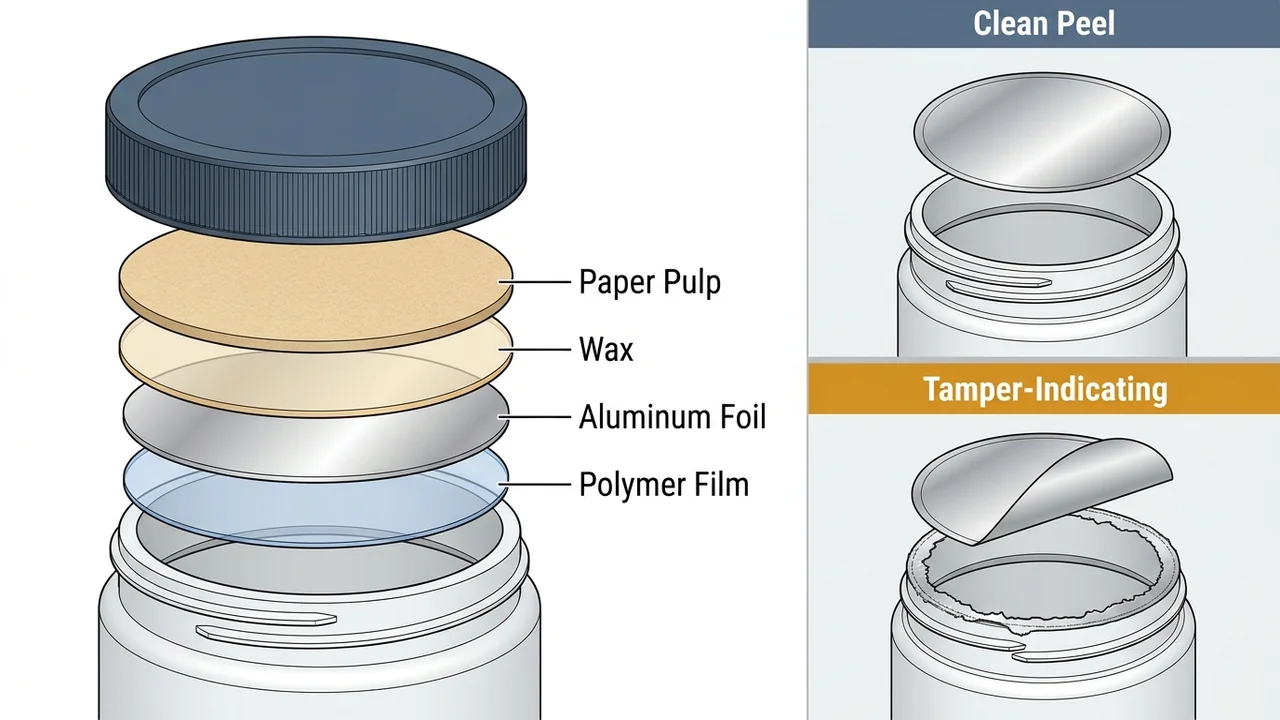
A typical multi-layer heat induction liner stacks four functional layers from the inside of the screw cap down to the jar rim:
- Paper pulp backing: The top layer is generally spot-glued inside the screw cap, absorbs melted wax during heating, and remains inside the closure as a secondary reseal cushion.
- Wax bonding layer: Holds the aluminum foil to the paper pulp during shipping and capping, then melts under eddy-current heat so the foil separates cleanly from the cap.
- Aluminum foil layer: Conducts induced eddy currents from the oscillating electromagnetic field and acts as the primary vapor and contamination barrier.
- Polymer heat-seal film: Laminated to the underside of the aluminum foil, this thermoplastic layer softens, flows onto the container lip, and solidifies into a hermetic weld as it cools.
How Does Induction Sealing Differ From Conduction and Capless Sealing?
Conduction sealing presses a heated hard metal plate directly against the container lip, introducing warm-up delays, complex temperature sensors, and zero compressibility for surface irregularities, whereas standard induction cap sealing operates non-contact through the closed cap with instant startup and capless induction sealing presses die-cut foil directly onto uncapped necks.
Choosing between cap-on induction, capless direct application, and conduction sealing depends on container finish tolerance and whether a threaded closure applies sealing pressure. When sealing a simple foil structure to glass, a rigid conduction plate provides no compressibility for glass surface-finish irregularities, while an induction sealer can use a compressible contact face to maintain a consistent bond and accommodate out-of-specification containers with minimal power resources.
In capless (direct application) induction sealing, reel-fed foil is die cut and transferred onto the container neck, or pre-cut foil is positioned on the rim, pressed down by the seal head, and bonded during the induction cycle without a cap.
| Sealing Method | Heat Transfer Mechanism | Closure Requirement | Startup & Thermal Control | Container Finish Tolerance |
|---|---|---|---|---|
| Cap-on induction sealing | Non-contact oscillating electromagnetic field inducing eddy currents in foil | Applied after filling and screw capping | Instant startup with minimal power resources | Accommodates out-of-specification rims and uses compressible contact faces on glass |
| Capless (direct application) induction | Electromagnetic induction cycle under a press-down seal head | No cap required during sealing; uses pre-cut or reel-fed die-cut foil | Instant induction cycle activation once foil is pressed onto neck | Foil is positioned and pressed directly onto the container neck |
| Conduction sealing | Direct contact from a heated hard metal plate | Applied directly to open container mouth | Delayed production from warm-up time; complex temperature sensors and heaters | Hard plate lacks compressibility for glass surface-finish irregularities |
How Do You Match an Induction Foil Seal Liner to Your Jar Resin and Tamper-Evidence Goal?
Match the liner’s bottom heat-seal polymer film to the exact jar resin—such as PE, LDPE, HDPE, PET, PP, or PVC—across commercial diameters from 15 mm to 120 mm, and select either a Clean Peel construction for residue-free dispensing or a tamper-indicating liner that leaves visible rim residue.
Resin Compatibility and Diameter Sizing
As The Cary Company notes for commercial heat induction liners, standard stock sizes span 15 mm to 120 mm and require polymer coatings formulated specifically for polyethylene (PE), low-density polyethylene (LDPE), high-density polyethylene (HDPE), polyethylene terephthalate (PET), or polyvinyl chloride (PVC) containers. On LINEVO’s Hookah Bottle and Tub Filling Line, Station 05 aluminum foil sealing is matched directly to liner material across PE, PET, and PP containers as well as container rim diameter to prevent syrup leakage.
Clean Peel vs. Tamper-Indicating Liners and Regulatory Benchmarks
Under 21 CFR 211.132, a tamper-evident package contains one or more indicators or barriers to entry that provide visible evidence to consumers if breached or missing. Section 211.132(b)(1) specifies that the tamper-evident feature must remain intact under reasonable handling during manufacture, distribution, and retail display, and section 211.132(c)(1) requires covered OTC retail packages to bear a consumer alert statement identifying the specific tamper-evident feature.
In FDA CPG Sec. 450.500, container mouth inner seals—made of paper, thermal plastic, plastic film, foil, or a combination—must be torn or broken to open and cannot be removed and reapplied without visible evidence of entry. The FDA guidance specifically notes that heat-induction seals on plastic containers offer higher tamper-resistance than adhesive-bonded seals, and that pressure-sensitive polystyrene foam container mouth seals are no longer considered effective tamper-resistant features because they can be removed and reapplied cleanly.
In practice, The Cary Company and packaging industry practice divide induction liners into two removal styles:
| Liner Type | Container Mouth Appearance After Opening | Typical Industry Use Case | Supported Resin & Diameter Scope |
|---|---|---|---|
| Clean Peel induction liner | Leaves no film or foil residue on the container mouth | Food and dispensing packs where loose rim residue could interfere with product removal | 15 mm to 120 mm liners matched to PE, LDPE, HDPE, PET, PP, or PVC |
| Tamper-indicating induction liner | Purposely leaves visible film or foil residue ring on the rim | Pharmaceutical bottles and retail tubs prioritizing unmistakable visual breach evidence | 15 mm to 120 mm liners matched to PE, LDPE, HDPE, PET, PP, or PVC |
| Pressure-sensitive polystyrene foam seal (non-induction) | Adhesive bond can lift and reapply without visible evidence | Not considered an effective tamper-resistant feature under FDA CPG Sec. 450.500 | Adhesive-only closure; lower tamper-resistance than heat-induction plastic welds |
How Do Screw Caps Hold the Foil Flat and What Causes Jar Seal Leaks?
On an automated rigid-container line, Station 04 screw capping applies and torques threaded plastic or metal lids to cap diameter, thread profile, and torque specification so the foil presses evenly against the jar lip before Station 05 induction sealing, while overheating or tobacco strands on the rim cause delayed leaks.
LINEVO’s automated Hookah Bottle and Tub Filling Line sequences bottle unscrambling, rotary indexing, dosing, Station 04 screw capping, Station 05 aluminum-foil induction sealing, wrap-around labeling, and bottle sorting. Uniform cap application holds the multi-layer liner flat against the plastic lip during heating and cooling so the melted polymer flows evenly around the full circumference.
Two process errors account for most jar seal leaks on wet shisha lines:
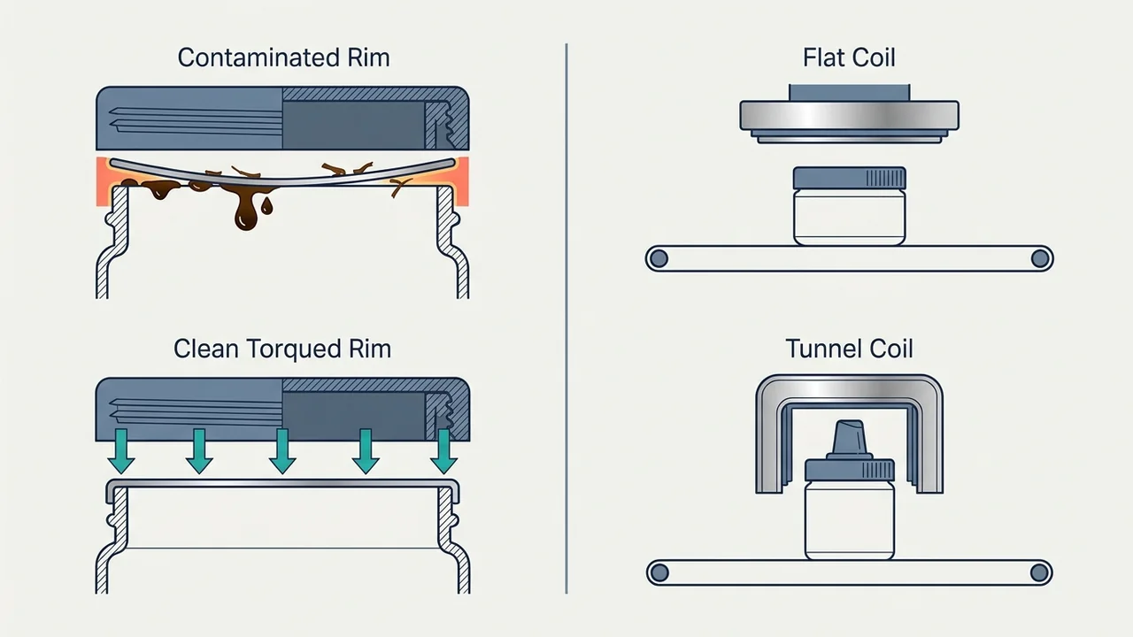
- Rim contamination before capping: Just as molasses or stray leaves trapped in a flexible bag seam cause weeping in shisha pouch sealing troubleshooting, wet tobacco strands sitting on a rigid tub or jar rim interrupt foil-to-plastic contact and compromise the induction aluminum-foil seal.
- Foil overheating from improper sealer sizing: Applying excess induction energy overheats the aluminum foil and damages both the polymer seal layer and protective barriers, creating weak or faulty seals that can fail even weeks after the initial sealing run.
When Should You Choose an Inline Conveyor vs. Handheld Induction Sealing Machine?
Choose a manual handheld induction sealer rated around 0.5 kW for low-volume batch runs, and step up to an inline conveyor induction sealing machine scaled up to 6 kW—paired with a flat coil for 20 to 120 mm flat caps or a tunnel coil for spouted caps—for continuous production.
As Pillar Technologies outlines in its induction sealer selection guidance, every induction sealing machine centers on two major components: the power supply and the sealing coil. Higher conveyor speeds and larger container mouth openings require higher kW ratings so the foil reaches weld temperature within a shorter pass under the head.
Modern inline systems have transitioned from water-cooled units to compact waterless (air-cooled) power supplies, eliminating water recirculation systems, filtration units, hoses, radiators, pumps, and flow switches. When integrating an inline head onto a rigid tub filling line, plan for 3 to 5 feet of straight, unimpeded conveyor space with the sealing coil mounted parallel to the conveyor and the entire sealing zone kept free of metal components to prevent accidental induction heating.
| Induction Sealer Parameter | Handheld / Manual Unit | Inline Conveyor System (Flat Coil) | Inline Conveyor System (Tunnel / Channel Coil) |
|---|---|---|---|
| Typical power supply rating | As low as 0.5 kW | Scaled with line speed and mouth size up to 6 kW | Scaled with line speed and mouth size up to 6 kW |
| Target closure style & size | Small-batch jars and manual benchtop runs | Standard flat caps from 20 to 120 mm in diameter | Spouted or dispensing caps requiring side-wall field coupling |
| Cooling architecture | Compact manual air-cooled housing | Waterless (air-cooled), eliminating pumps, hoses, and radiators | Waterless (air-cooled), eliminating pumps, hoses, and radiators |
| Conveyor mounting footprint | Benchtop operator station | 3 to 5 feet of straight, metal-free conveyor space | 3 to 5 feet of straight, metal-free conveyor space |
How Do You Inspect Induction Foil Seal Integrity on a Production Line?
Automated lines verify induction foil seals using inline seal-integrity detectors that flag missing foil liners, loose or misaligned caps, and stalled bottles, complemented by magnetic-field pickup coils that dynamically predict foil heating and peel-off strength uniformity, alongside Factory Acceptance Testing (FAT) rim cleanliness checks.
Combining automated sensors with pre-shipment sample testing and FAT verification catches both immediate capping defects and latent bond weaknesses before containers enter distribution:
| Inspection Checkpoint | Defect or Variable Detected | Where It Runs on the Line | Engineering Action |
|---|---|---|---|
| Pre-capping rim check (FAT) | Wet tobacco strands sitting on the rigid tub or jar rim | Between dosing and Station 04 screw capping | Verify clean rim presentation during FAT before finalizing nozzle and indexing settings |
| Inline seal-integrity detector | Missing foil liner, loose cap, misaligned cap, or stalled bottle | Downstream of Station 05 induction sealing head | Reject or alarm affected containers automatically for quality control |
| Magnetic-field strength monitor | Fluctuations in induction head field strength via pickup coils | At the induction sealing head | Quantify post-weld heating uniformity and predict foil peel-off strength |
| Sealer sizing & thermal check | Overheated foil damaging seal layer or protective barriers | Line commissioning and SKU changeover | Match power supply kW and coil design to opening diameter to prevent delayed leaks |
Frequently Asked Questions
What is an induction foil seal and how does it work?
An induction foil seal uses an oscillating electromagnetic coil to induce eddy currents inside the aluminum foil layer of a cap liner after filling and screw capping. The heated foil melts the wax layer into the paper pulp backing and fuses the bottom polymer film onto the container rim as it cools, forming a hermetic seal without heating the product.
What is the difference between Clean Peel and tamper-indicating induction liners?
Clean Peel induction liners peel away cleanly without leaving film or foil residue on the container mouth, making them preferred for food and dispensing applications where residue could interfere with the product. Tamper-indicating liners purposely leave visible film or foil residue on the jar rim to alert consumers to potential tampering.
Why are heat-induction inner seals preferred over pressure-sensitive foam seals?
According to FDA CPG Sec. 450.500, heat-induction inner seals on plastic containers offer higher tamper-resistance than adhesive-bonded seals because they must be torn or broken to open. Pressure-sensitive polystyrene foam seals are no longer considered effective tamper-resistant features because they can be removed and reapplied with no visible evidence of entry.
Can overheating an induction foil seal cause leaks later?
Yes. Overheating the aluminum foil damages the heat-seal polymer layer and protective barriers, which can produce faulty seals that fail weeks after the initial sealing process. Sizing the power supply and coil properly for container opening diameter and line speed prevents thermal damage.
How much conveyor space does an inline induction sealing machine require?
Installing an inline conveyor induction sealer typically requires 3 to 5 feet of straight, unimpeded conveyor space. The sealing coil must be mounted parallel to the conveyor, and the sealing zone must stay free of metal components to prevent accidental heating.
Sources
- Wikipedia — Induction Sealing (Electromagnetic Eddy Currents, Multi-Layer Liners, Capless Sealing, Conduction Comparison, and Magnetic Field Monitoring)
- eCFR — 21 CFR 211.132 Tamper-Evident Packaging Requirements for Over-the-Counter Human Drug Products
- U.S. FDA — CPG Sec. 450.500 Tamper-Resistant Packaging Requirements for Certain Over-the-Counter Human Drug Products
Configure Your Shisha Packaging Line with LINEVO Engineers
Send your shisha tobacco pack format, target gram weight, and required speed on WhatsApp to receive technical drawings, trial videos, and an itemized factory quotation, or check our RFQ preparation checklist.
Get Quote via WhatsAppBrowse all Shisha Packaging Guides